PPAM Aid Prosthetic
Introduction
A Pneumatic Post Amputation Mobility (PPAM) Aid is a form of early walking aid (EWA) that is used for the rehabilitation of lower-extremity amputees immediately after healing from their operation. This is to initiate the gait training process by assisting the patient to walk while in an upright position, while at the same time not inducing any pressure that may inflict pain on the stump. EWAs are not intended to be used as long-term prosthetics, but rather a transition from post-operation to prosthetic use. The pneumatic aspect comes from the inflatable bags that act as a cushion between the user’s body and the aid’s frame. Other than the physical aspect of the PPAM Aid, early gait training also benefits the patient psychologically. The adjustable pneumatic bags combined with the scalable design of the frame makes the PPAM Aid a reasonable option for several patients.
The PPAM Aid is made to be usable by both below-knee/transtibial and above-knee/transfemoral patients. However, it is worth noting that in both designs, the aid takes the shape of a leg with a locked knee; the aid’s frame is straight and fixed. This does not manifest a natural gait, and instead encourages the users to utilize a gait, such as limping, that accounts for the aid’s rigid structure. However, there have been attempts to address this problem. The Amputee Mobility Aid (AMA) is a form of an early walking device that was developed to allow transtibial amputees to manifest a more natural gait (Barnell et al, 2009). The hinge on the AMA allows the patient to change the movement of the lower portion of the walking aid by engaging their knee, thus producing a natural gait that eases the process of using an EWA.
This consideration for transtibial patients can also be applied to transfemoral patients by redesigning the PPAM Aid such that a natural gait is still possible. This could be accomplished with the addition of a knee joint that stimulates the knee flexion that occurs during the gait cycle.
Scope & Limitations
Scope
-
Assembly of components for a functional EWA
-
Simple analysis of forces acting on the components
Limitations
-
This design paper does not include creating a prototype
-
This design is limited to non-electronic components in order to minimize cost
Assumptions
To initiate the design process, a user of the EWA must be conceptualized. To approximate the measurements of an adult patient, the mean anthropometric measurements of Filipino manufacturing workers will be used (Del Prado-Lu, 2007). From the data gathered in the study, the mean height is 160.465 cm, the mean knee height is 47.805 cm, and the mean hip height is 86.5 cm; these will be some of the assumed anthropometric measurements of the user. Del Prado-Lu also found that 92.7% of respondents weigh less than 80 kg, thus it will be assumed that the user is 80 kg. According to Devinuwara, Dworak-Kula, and O’connor (2018), the residual bone after a transfemoral amputation must be about 7.5 - 10 cm above the patella in the knee joint; it will be assumed that the user’s residual bone in the stump is 10 cm above the patella.
For structural analysis, a safety factor of 2 will be assumed. According to Engineering ToolBox, a safety factor range of 1.5 - 2 is recommended for reliable materials where loading and environmental conditions are not severe.
Material Selection
The criteria for materials used in making prosthetics is strict, since high specific strength, relatively low density, and good resistance to corrosion are needed for a prosthetic to be viable. For this reason, Ti-6Al-4V titanium alloy will be used for all components consisting of metal.
Frame Design
The first component of the redesigned EWA that must be modified is the metal frame that holds the inflatable pneumatic bag. In the original design, the frame spans from the upper thigh down to the connection at the rocker or prosthetic foot. To incorporate the knee joint, the frame must end just above where the knee joint would be. Another notable feature of the original PPAM Aid’s frame is that it is tapered and the angle of tapers increases nearer to the bottom of the frame. The frame must also be wider such that it can accommodate both the stump and the inflated pneumatic bag, but not too wide that it would impede the user’s gait. Another feature of the original PPAM Aid’s frame is that there is a lot of clearance below the stump so that the stump would not come in contact with any components that could cause discomfort; this will also be taken into account in designing the modified frame. To further prevent the residual limb from coming into contact with any of the EWA’s components, the

Figure 1
frame’s members are placed laterally from the limb. However, a ring is placed throughout the circumference of the frame in the upper thigh area in order to hold and secure the pneumatic bags.
Out of the several parts of this component, the part that could bring up concern regarding failure would be the frame’s lateral members. The technical drawing of this part is shown in Figure 3. This shape is similar to an inverted version of the gabled frame that is often used in construction. Hence, the method of computing for the effective length of a gabled frame with tapered members will be used for analysis (Saffari & Rahgozar, 2010).
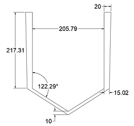
Figure 2

Figure 3
To determine if the metal frame’s members do not buckle due to the user’s weight, buckling analysis must be performed on this part. Using Euler’s formula
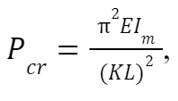
where E is the material’s elastic modulus, I is the moment of inertia of the middle section of the column, K is the effective length factor, and L is the length, the critical load at which buckling occurs, P , can be determined. According to Aerospace Specification Metals Inc., the elastic modulus of Ti-6Al-4V is 113.8 GPa. Before the moment of inertia is determined, it must be noted that this part of the metal frame has a constant depth of 15 mm, which will be used as the height parameter in computing for the moments of inertia at all sections. The bottom most part of the member is considered to be the column’s midsection, thus the moment of inertia at the midsection of the column can be calculated as
m
cr

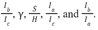
The length to be used for Euler’s formula is denoted as S in the top right of Figure 3; in the case of the metal frame member, this length is 225.79 mm. The only other parameter needed is the effective length factor, which can be determined using the dimensionless chart in Figure 3 and the needed parameters:
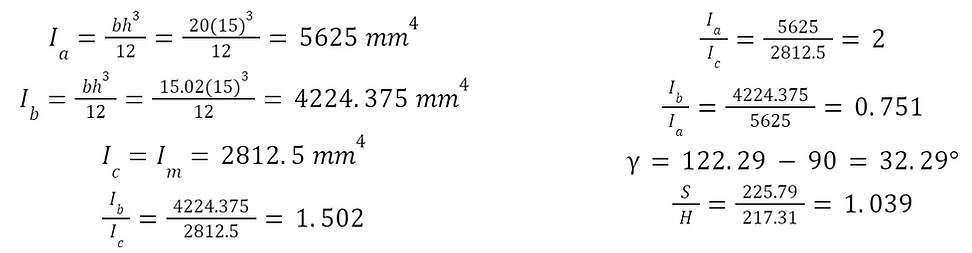
With these parameters, the dimensionless chart can be used. This is first done by projecting the Ib/Ic to the corresponding curve in the top right graph. This intersection is then projected downward to the corresponding S/H in the bottom right graph, to the corresponding Ia/Ic in the bottom left graph, and then up to an intersection with the projection of the Ib/Ia value in the top left graph. From this method, it is determined that the corresponding effective length factor is approximately 1.2. The critical load can now be calculated using Euler’s formula.
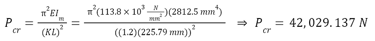
Comparing this to the bodyweight of the conceptualized user and accounting for the factor of safety,

Since the critical load is significantly higher than the load from the user’s weight, it is safe to conclude that the metal frame members will not buckle due to the user’s weight.
Knee Joint
For the knee joint component to be used, a passive mechanism shall be utilized in order to dismiss the need to add any additional electronics or other components, in the case of active mechanisms. There are several existing passive knee joint prosthetic mechanisms such as the simplified automatic stance phase lock mechanism (Andrysek et al., 2011) and the three-axis latch mechanism (Arelekatti & Winter, 2015). However, considering the nature of an EWA, the mechanism to be used is the position and weight activated passive prosthetic knee mechanism (Ramakrishnan et al., 2015). Out of all the possible mechanisms, the position and weight activated passive mechanism is the simplest and easiest to manufacture.
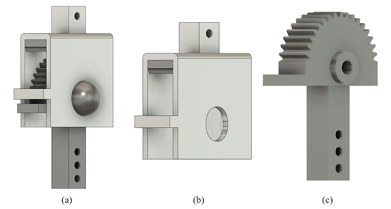
Figure 4
Shown in Figure 4a is an approximate model of the chosen knee joint mechanism. Its two main parts are distinguished by the difference in material colors. These parts, the femur and the shank, can also be seen in Figure 4b and Figure 4c, respectively. The top part of the femur connects to the frame that holds the pneumatic bag, while the bottom of the shank connects to the lower leg and prosthetic foot. The multiple holes at the bottom provide adjustability to the overall length of the EWA. The spur gear portion of the shank allows for the shank to lock onto the rack located in the femur’s housing. The protruded rings on either side of the shank and the cutout slots on the femur allow the shank to move linearly and rotate relative to the femur. Both femur and shank components have stoppers in front that come into contact when the femur and shank are meant to lock into each other.
Figure 6 displays the stages that the knee joint mechanism goes through during the gait cycle. A more detailed representation of the gait cycle while using the knee joint is shown in Figure 6. When the user is standing still or during the phases in Figures 6(a), 6(f), 6(g), and 6h), their weight is acting on the knee. This makes the femur go down and lock on to the shank because of the rack and pinion. This lock also prevents the shank from rotating and causing the lower leg to swing. This interaction is depicted in Figure 5a. The interaction depicted in Figure 5b occurs when the user initiates their gait as seen in 6(e). The user’s weight is transferred from both legs onto the stepping leg, thus relieving the knee mechanism of their weight. This causes the rack and pinion to unlock and the shank moves down due to gravity, allowing the shank to freely rotate. Figure 5c takes place when the user swings their residual limb forward, as in Figures 6(c) and 6(d). Towards the end of this swing in Figure 6(b), the shank rotates forward until the stoppers hit as seen in Figure 5d.
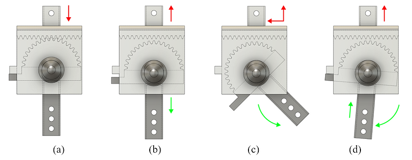
Figure 5
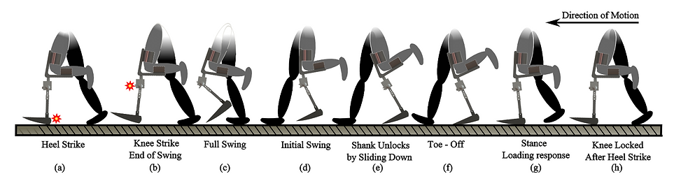
Figure 6
Lower Leg and Foot
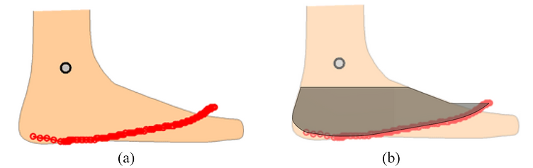
Figure 7
Based on the total lengths of the previous two components, the user’s hip height, and position of the frame in relation to the user’s hip, the lower leg and foot must have a total length of 21.6114 cm. The prosthetic foot to be used is a rocker that closely resembles the roll-over shape of able-bodied subjects, as seen in Figure 7a (Hansen et al., 2004). This shape is scaled to the mean foot length of 24.025 cm found by Del Prado-Lu. From this scaled roll-over shape, the shape of the prosthetic foot is approximated in Figure 7b. The length of the lower leg is determined by the height of the rocker and the total length of the lower leg and foot. Taking into account the adjustable connector at the shank and the connector at the prosthetic foot, the maximum length of the lower leg is 20.057 cm. The designed foot and lower leg assembly is shown in Figure 8.
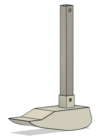
Figure 8
To test if the lower leg portion is stable, buckling analysis can be performed, where the lower leg is considered a column with fixed ends. Using Euler’s Formula
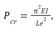
where E is the material’s elastic modulus, I is the moment of inertia, and Le is the effective length, the critical load at which buckling occurs, P , can be determined. The effective length of a column with fixed ends is simply half of the column’s length. According to Aerospace Specification Metals Inc., the elastic modulus of Ti-6Al-4V is 113.8 GPa. The lower leg’s cross sectional area is a hollow square, so moment of inertia can be calculated,

Given all of these values, the lower leg’s critical load can be computed,

Comparing this to the bodyweight of the conceptualized user and accounting for the factor of safety,

Since the critical load is significantly higher than the load from the user’s weight, it is safe to conclude that the lower leg will not buckle due to the user’s weight.
Bending Stress at Heel Strike
A point of the gait cycle wherein the structural analysis of the components can be analyzed is the heel strike. At heel strike, the knee is fully extended and the leg is at an angle. Due to the orientation of the leg, the ground reactive force (GRF) applies a bending stress on the leg. At heel strike, the foot is oriented at 25° in relation to the floor and the ankle is maintained at a neutral position, keeping the foot at 90° relative to the leg (Perry, 2002). This means the leg would be oriented at 65° relative to the floor.
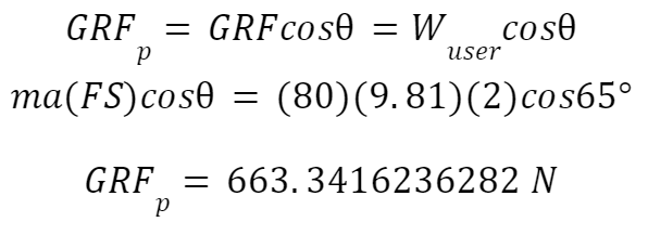
Shown in Figure 10 is the assembled EWA as it hits heel strike during the gait cycle. Also shown in this figure are the point where the GRF acts on the EWA and the distances from this point to the center of masses of the lower leg and frame; these are the components that need to be checked for bending. Since the GRF is not perpendicular to the EWA, it is broken down into two components: one perpendicular to the EWA, and the other normal to the EWA. Assuming the GRF is equal to the force due to the weight of the user, the component normal to the EWA can be disregarded since it applies a lower axial load than what was previously analyzed. Hence, only the GRF component perpendicular to the EWA is considered for analysis.
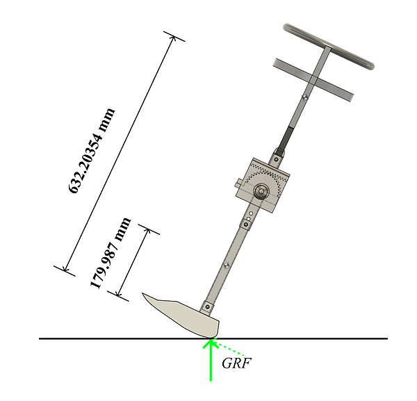
Figure 9
The component in question can be determined using its angle in relation to the GRF,
This component will now be used in undergoing bending analysis for both the lower leg and frame. It is also important to note that the factor of safety is already considered in this component. The bending stresses from both components will be compared to Ti-6Al-4V’s yield strength of 880 MPa (Aerospace Specification Metals Inc., n.d.).
The first component to be analyzed is the lower leg. As found earlier during buckling analysis, the moment of inertia for the lower leg’s cross section is 11,833.864192 mm . Another parameter needed in order to find the bending stress is the distance to the neutral axis, which is found to be 10.32 mm after checking the sketch on Fusion 360. The distance from the force to the lower leg’s center of mass is also known, so the acting moment can be determined.
4

This is significantly lower than Ti-6Al-4V’s yield strength of 880 MPa, thus the lower leg will not yield due to the bending stress at heel strike.
The other component that must be considered for bending stress is the metal frame. After checking the model of the frame in Fusion 360, it was found that the metal frame’s members have a width of about 16.861114 mm each in the same plane as the center of mass, thus the moment of inertia at this cross section can be calculated as
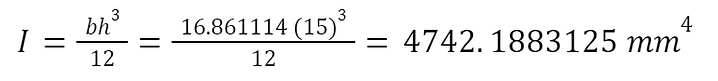
The bending stress can now be solved for,

This bending stress is also lower than Ti-6Al-4V’s yield strength of 880 MPa, so it can be concluded that neither analyzed parts will yield due to the bending stress at heel strike.
Shear Stress at Pins
There are two sizes of pins used for this design; the big pin that ensures connection between the femur and shank of the knee joint and the three smaller pins that connect the frame to the femur, the shank to the lower leg, and the lower leg to the prosthetic foot. The shear stress experienced by these pins will be compared to the ultimate shear strength of Ti-6Al-4V, 550 MPa (Aerospace Specification Metals Inc., n.d.). The bigger pin has a diameter of 12.664 mm and the smaller pins have a diameter of 8.169 mm. The shear stress experienced by these pins due to the user’s weight can then be determined using the formula for maximum shear stress in circular beams,
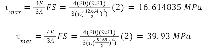
Since the shear stresses experienced by the pins are significantly lower than the shear strength, it is assured that the pins will not yield due to the user’s weight.
Materials and Manufacturing Cost
To determine the overall cost for the materials, the total mass of all components should be calculated. Since the model was created in Fusion 360, the program’s component properties menu was referred to for each component’s volume. Almost all components are made from the Ti-6Al-4V titanium alloy, which is available in the material library of Fusion 360. Thus, the mass of each component was already available under the components properties menu. The gathered volumes and masses of each component can be found in the table below.
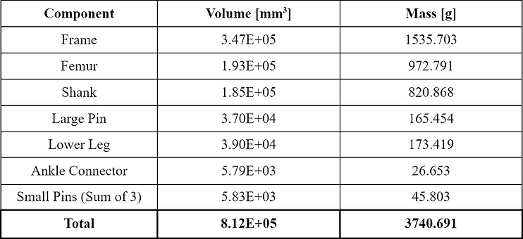
The company Xi'an Zhonghe Zheng Laboratory Equipment Co., Ltd. offers Ti-6Al-4V titanium alloy at $20 per kilogram. The total mass of titanium alloy needed is rounded up to the nearest kilogram. Solving for the total cost of metal components,

The only other component not made from the titanium alloy is the prosthetic foot/rocker. The material used for this component is delrin, which is also commonly known as acetal. Acetal resin is also a material found in Fusion 360’s materials library, so the prosthetic foot’s volume and mass are found to be 5.905E+05 mm and 841.497 g, respectively. Suzhou Duoqi Material Technology Co., Ltd. is selling this delrin material for $13.43 per kilogram. The mass of delrin material needed is rounded up to the nearest kilogram. Solving for cost of delrin material,
3
In terms of manufacturing, the components for the EWA will need to be custom manufactured, thus a manufacturing cost of PHP 5,000 is estimated for the custom components. This brings the total cost of materials and manufacturing to approximately PHP 9,792.96.
Conclusion
Affordable EWAs that assist transfemoral patients to get used to a natural gait while recovering from the operation are possible to manufacture. The design discussed is a prime example of this, as it has been found to be able to withstand the forces due to movements in the gait cycle. Figure 10 depicts the full assembly as modeled in Fusion 360. This design presents good manufacturability since the components are not too complex and each component can be scaled individually in order to perfectly fit any patient.
It is important to reiterate that no electronic components were used in order to minimize the manufacturing cost. However, there are other passive mechanisms for the knee joint that could be considered. This knee joint mechanism was chosen for its simplicity and the fact that an EWA is meant to be used short term. For future designs relating to this, it is recommended that a prototype is created so that the design could be field tested.
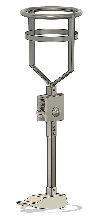
Figure 10
References
Ortho Europe. (2017, Feb 2). PPAM aid fitting tutorial [Video]. YouTube. https://www.youtube.com/watch?v=N1n88OvUWtI
Barnett, C., Vanicek, N., Polman, R., Hancock, A., Brown, B., Smith, L., & Chetter, I. (2009). Kinematic gait adaptations in unilateral transtibial amputees during rehabilitation. Prosthetics & Orthotics International, 33(2), 135–147. https://doi.org/10.1080/03093640902751762
Del Prado-Lu, J. L. (2007). Anthropometric measurement of Filipino manufacturing workers. International Journal of Industrial Ergonomics, 37(6), 497–503. https://doi.org/10.1016/j.ergon.2007.02.004
Devinuwara, K, Dworak-Kula, A and O'Connor, RJ (2018) Rehabilitation and prosthetics post-amputation. Orthopaedics and Trauma, 32 (4). pp. 234-240. ISSN 1877-1327
Factors of safety. Engineering ToolBox. (n.d.). Retrieved from https://www.engineeringtoolbox.com/factors-safety-fos-d_1624.html
Saffari, H., Rahgozar, R., & Jahanshahi, R. (2008). An efficient method for computation of effective length factor of columns in a steel gabled frame with tapered members. Journal of Constructional Steel Research, 64(4), 400–406. https://doi.org/10.1016/j.jcsr.2007.09.001
Titanium Ti-6Al-4V (Grade 5), Annealed. Aerospace Specification Metals. (n.d.). Retrieved from http://asm.matweb.com/search/SpecificMaterial.asp?bassnum=MTP641
Andrysek, J., Klejman, S., Torres-Moreno, R., Heim, W., Steinnagel, B., & Glasford, S. (2011). Mobility function of a prosthetic knee joint with an automatic stance phase lock. Prosthetics & Orthotics International, 35(2), 163–170. https://doi.org/10.1177/0309364611408495
Arelekatti, V. N., & Winter, A. G. V. (2015). Design of a fully passive prosthetic knee mechanism for transfemoral amputees in India. 2015 IEEE International Conference on Rehabilitation Robotics (ICORR). https://doi.org/10.1109/icorr.2015.7281224
Ramakrishnan, T., Lahiff, C.-A., Marroquin, A. K., & Reed, K. B. (2015). Position and weight activated passive knee mechanism. Volume 3: Biomedical and Biotechnology Engineering. https://doi.org/10.1115/imece2015-53229
Hansen, A. H., Childress, D. S., & Knox, E. H. (2004). Roll-over shapes of human locomotor systems: Effects of walking speed. Clinical Biomechanics, 19(4), 407–414. https://doi.org/10.1016/j.clinbiomech.2003.12.001
Bowker, J. H., Michael, J. W., & Perry, J. (2002). 13 - Normal Gait. In Atlas of limb prosthetics: Surgical, Prosthetic, and rehabilitation principles. essay, Mosby Year Book.